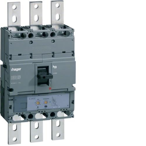
Moulded Case Circuit Breaker h1000 3P 50kA 800A LSI HNE800H

EAN
3250613349738
Packaging
1 Piece

Technical properties

Archi­tec­ture
  • Number of poles
    3 P
Func­tions
  • Complete device with protec­tion unit
    Yes
  • Trip Unit
    LSI
  • Integ­rated earth fault protec­tion
    No
Config­ur­a­tion
  • Number of modules
    12
Main elec­trical features
  • Rated oper­a­tional voltage Ue
    220 / 690 V
  • Frequency
    50/60 Hz
Voltage
  • Rated insu­la­tion voltage
    800 V
  • Rated impulse with­stand voltage
    8 kV
  • With under voltage release
    No
Elec­tric current
  • Rated current
    800 A
  • Rated ulti­mate short-­cir­cuit breaking capa­city Icu under 690V AC IEC 60947-2
    20 kA
  • Thermal protec­tion nob setting xIN
    0.4 / 0.5 / 0.63 / 0.9 / 0.95 / 1
  • Breaking capa­city on 1 pole for IT 230V NF 60947-2
    51 kA
  • Breaking capa­city on 1 pole for IT 400V NF 60947-2
    9 kA
  • Rated service breaking capa­city Ics AC according IEC 60947-2
    100 %
  • Rated ulti­mate short-­cir­cuit breaking capa­city Icu under 230V AC IEC 60947-2
    85 kA
  • Rated ulti­mate short-­cir­cuit breaking capa­city Icu under 240V AC IEC 60947-2
    85 kA
  • Rated ulti­mate short-­cir­cuit breaking capa­city Icu under 400V AC IEC 60947-2
    50 kA
  • Rated ulti­mate short-­cir­cuit breaking capa­city Icu under 415V AC IEC 60947-2
    50 kA
  • Rated ulti­mate short-­cir­cuit breaking capa­city Icu under 440V AC IEC 60947-2
    45 kA
Current correc­tion factors
  • Correc­tion factor of rating current for 2 devices placed side-by-side
    1
  • Correc­tion factor of rating current for 3 devices placed side-by-side
    1
  • Correc­tion factor of rating current for 4 and 5 devices placed side-by-side
    1
  • Correc­tion factor of rating current for 6 devices placed side-by-side
    1
Power
  • Total power loss under IN
    153.6 W
  • Power loss per pole at In
    51.2 W
Trip­ping
  • Trip­mode
    LSI
  • Thermal protec­tion trip time
    5 / 10 / 11 / 19 / 21 / 29 ms
  • Time of response when opening
    10 ms
Elec­trical specific­a­tions
  • Magnetic trip delay time
    100 to 200 ms
Endur­ance
  • Elec­tric endur­ance in number of cycles
    1000
  • Number of mech­an­ical oper­a­tions
    4000
Install­a­tion, mounting
  • DIN rail mounting with optional adapt­ator
    No
Connec­tion
  • Type of connec­tion
    Terminal
Settings
  • Range of the magnetic adjust­ment
    4480 / 5600 / 7000 / 8960 / 9600 / 9600 / 9600 A
  • Magnetic protec­tion nob setting xIN
    2.5 / 5 / 10
  • Setting type In or Ith
    IrTh
Equip­ment
  • Number of auxil­iary contacts as normally closed contact
    0
  • Number of auxil­iary contacts as normally open contact
    0
  • Number of auxil­iary contacts as change-over contact
    0
  • Motor drive optional
    Yes
Use cases
  • Category of use
    A
Stand­ards
  • Standard text
    IEC 60947-2
Use condi­tions
  • Oper­ating temper­ature
    -25…70 °C
  • Alti­tude
    2000 m
  • Air humidity protec­tion
    for all climates
  • Stor­age/trans­port temper­ature
    -35…70 °C